10934 East 55th Place
Tulsa, OK 74146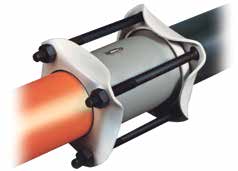
Style 711: Bolted Restraining Couplings
Ordinary mechanical couplings provide only a seal on the pipe end when installed. They do not prevent the pipe from pulling out of the coupling.
The Style 711 provides both a seal and a restraint
- As the coupling bolts are tightened, the coupling followers compress the gaskets and then force the steel grip rings to collapse around the pipe end, providing a restraint
- This gripping action increases as the pipes attempt to come out of the coupling
Meets or exceeds the requirements of D.O.T. Code 192.283(b) provided the proper Dresser reinforcing insert stiffener is used in the P.E. pipe ends.
Conductive vs. Insulating Coupling Design
- Conductive: used on lines that are to be electrically joined so as to share cathodic protection
- Insulating: used on lines that are to be electrically isolated (or sectionalized) for cathodic protection, or for insulating between pipe and dissimilar metals
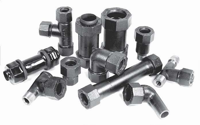
Style 90: Universal Products
The “universal” Style 90 locking design creates a positive pipe restraint. As the nut is tightened, it compresses the gasket, which forces the steel lock rings to collapse around the pipe. The gripping action increases as the pipe attempts to move out of the coupling.
Available in insulated restraining couplings
- Features a restraining end and an insulated restraining end
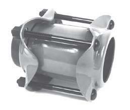
Style 39: Coupling
The Dresser coupling consists of one cylindrical middle ring, 2 follower rings, 2 resilient gaskets and a set of steel track-head bolts. The middle ring has a conical flare at each end to receive the wedge portion of the gaskets. The follower rings confine the outer ends of the gaskets. Tightening bolts draw the follower rings toward each other, compressing the gaskets in the spaces formed by the follower rings, middle ring flares, and pipe surface providing a flexible, leak-proof seal
Style 39 Couplings are widely used on lines which are to be electrically isolated for cathodic protection, or for insulating between pipe of dissimilar metals. One pipe end is completely insulated from the coupling and opposite pipe end, while the armored gasket on the other end bonds the coupling to the pipe where it can share cathodic protection currents. Can be supplied with insulating features on both ends if required.
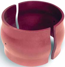
Style 110: Reinforcing Sleeve
Split reinforcing sleeve for repair of welded joints
Ready for field welding without preheating, using ordinary field welding procedures. All sleeves are factory prepared with standard welding bevel, machine flame cut for uniformity and ease of welding, and come with a drilled vent hole to preclude pressure build-up between sleeve and pipe
Minimum yield strength 50,000 psi, ultimate strength 70,000 psi.
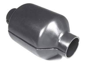
Style 220: Reinforcing Sleeve
Similar to the style 110, the 220 encompasses a “pumpkin” sleeve design and are commonly used to repair corrosion pits and stress cracks and offer permanent repair over leaking couplings, flanges, valves, or screw collars
Minimum yield strength 50,000 psi, ultimate strength 70,000 psi
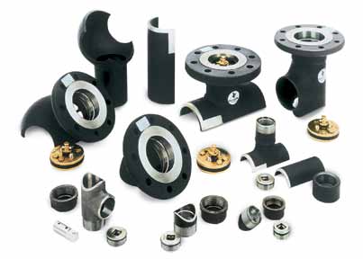
Blackhawk: Hot Tap & Line Stop Fittings
Pressure control fittings for threaded 1-1/4”–3” and flange fittings from 4”-12”
LS-2 fittings are designed, tested and manufactured to meet and exceed the code area replacement requirements for pressure containment per ASME/ANSI B31.8
Split sleeve fitting are also manufactured with side outlet, spherical configurations and with a weld neck flange for hot tapping
When field welding is not an option, Dresser offers the Style 50 mechanical sleeve integrated with Style LS-2 fittings with side outlets for hot tap service connections
